The engineering notebook
The machine is on the main page. This is the evidence under it: what MITS's own documents say, what was measured, which sources disagree, and which questions stayed open. Nothing here is needed to work the switches. Everything here is why the switches can be trusted.
What MITS bought, which is how the panel is checked
The panel's layout was measured off a photograph, which is one source and could be one mistake. MITS also published a parts list, effective 1 March 1975, and the Display/Control board line items settle three things a photograph can only suggest.
| 36 × RL-21 LED | at 60 cents each. This page draws 36 lamps: two flags, eight status and eight data on the top row, two flags and sixteen address on the bottom. The count is not an interpretation of a photograph, it is what was ordered. The part number had been an open question here since the beginning. RL- is Litronix's own prefix for discrete red lamps, which their 1982 catalogue confirms: RL-2, RL-50, RL-54, RL-209, RL-2000 and more, all red indicator lamps. RL-21 is not itself in the 1982 edition, seven years after the Altair shipped, but a 1975/76 distributor databook page settles it. That page is headed for the RL20 and RL21 red L.E.D.s together, under the Litronix masthead, and gives gallium arsenide phosphide in a red diffusive moulded lens, 0.7 millicandela typical at 20 milliamps, and a 180° viewing angle that the sheet calls extremely suitable for panel use. The brighter RL20 sibling ran 1.2; MITS bought the dim one, which fits sixty cents. The designation is MITS-wide, not a one-off line item: the machine's own assembly manual calls for “36 RL-21 LED's” on the Display/Control Board, and draws the package with its cathode and anode called out. |
|---|---|
| 17 × switch ST-1-1-C | at $2.35. The ones that stay where you put them: sixteen address switches and the power switch. |
| 8 × switch ST-1-3-C | at $2.45. A different part, and there are exactly eight control switches, which are the ones that spring back to the middle. This page already drew them that way from photographs. The assembly manual then says it outright: “Eight of these are momentary contact SPDT switches and seventeen are latching type SPDT switches.” |
| 1 × 8080, Intel | where every other line has a price, this one says Factory Quote. |
The boards, photographed
The cage on the main page draws its cards, because drawings can be consistent where surviving photographs cannot. But cleanly licensed photographs of the real boards exist for some of them, and they belong here, where the evidence lives. All five below are by Eric Smith, from his own machines, and carry a licence that permits reuse; each is linked to its source. They are resized and otherwise untouched.
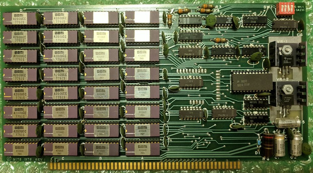
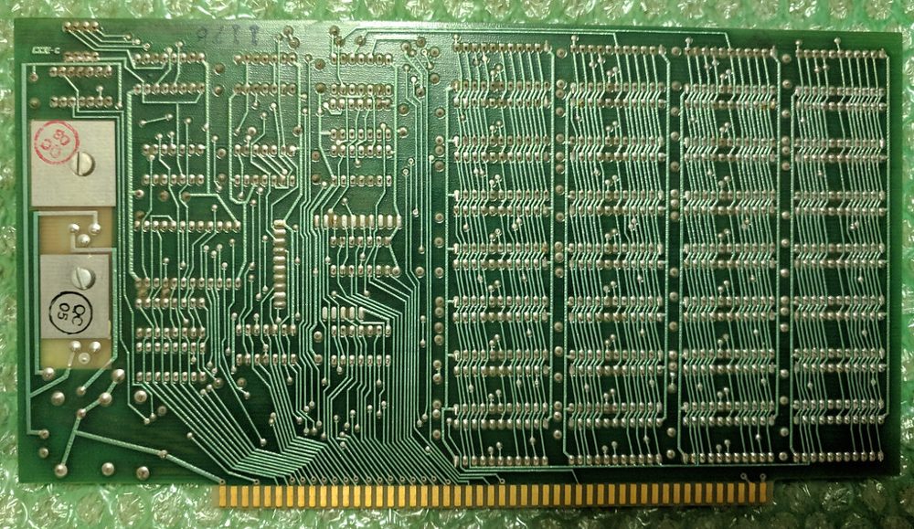
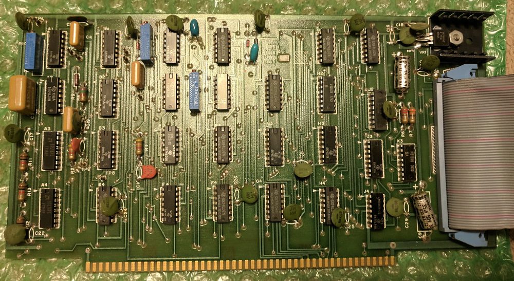

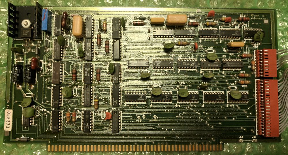
Public-domain advertisement scans exist for several more boards — the 88-2SIO with the 88-PIO in Byte's January 1976 issue, the 4K static board that April, the 88-80LP's control card in December 1975, and a labeled 16MCS in Kilobaud, January 1977 — and the ledger of what is licensed, what is not, and what was searched without result lives in the project's research notes. Nothing cleanly licensed has been found for the 88-ACR, the 88-VI, a labeled 88-PMC, the small memory boards or the 88-EC, which is why the cage stays drawn.
The switches were silver after all
In August 2026 this page drew the switches in four colours: magenta for 15 down to 8, cream for 7 down to 0, teal for the controls and black for the two AUX switches. It said MITS had colour-coded the sense boundary at the factory. That came from one photograph of one machine, and it was stated with more confidence than one photograph earns. It was wrong, and the switches are drawn as bare chrome again.
The evidence is a parts list and a survey of photographs. MITS's Altair 8800 assembly manual lists 17 switches of type ST-1-1-C, the sixteen address switches and power, and 8 of type ST-1-3-C, the momentary ones. It has no line for a cap, boot or coloured handle. Mike Douglas's 8800b restoration notes name the maker as American Switch, later bought by APEM. APEM's catalogue gives the actuator of that series as brass, bright nickel or chrome plated. The red in the same catalogue is the plastic case behind the panel, which you cannot see from the front. The flat baton matches the catalogue's flatted actuator option, which is our reading and not something a source says.
We looked at nine machines at full resolution. Eight are bare metal on every switch, including a 1975 unit from the first hundred, the Smithsonian's and Living Computers'. The one exception is a display unit at the Computer History Museum, with coloured ball handles on the seven control switches only, and bare metal on all sixteen address switches. Nothing documents them. We read them as a later repair, which is an inference. The red and blue nibble colouring many people remember belongs to the IMSAI 8080, not to the Altair. On the Altair the sense boundary is marked by the printed rule and the grouping segments, which this page draws.


.jpg)

Two things about drawing chrome. It has almost no colour of its own, because it mirrors what is around it, so on a dark panel the lever reads darker than the panel, with one narrow bright band and a blown-white spot at the tip. A pale silver bar is what makes it look like plastic. And the pose: the lever pivots in the plane of the panel, so both ends of the throw come toward you, and from above the row a lever thrown down is long, one thrown up is short, and one at rest is nearly a dot. The old drawing made up and down mirror images. The bands are fitted to chrome measured on the Living Computers photograph and are ours, not pixels lifted from it.
One earlier claim stays retracted. This page used to add that there is a bright ring of bare metal at the base of every switch. There is not one on the reference photograph: the ring around each toggle hole is a little darker than the panel, not brighter, so that claim had nothing behind it.
What we could not settle: what the C in ST-1-1-C means, whether the lever length changed with the year, where the coloured balls at the museum came from, and how bright the ring around each hole should be. The Living Computers photograph shows a bright hex nut, while the reference photograph shows a darker ring, so the holes are left as they were.
Why the lamps blur, from the schematic
This is the part of the page most likely to be compared against a memory or a video, so it is worth saying exactly what the circuit does. On drawing 880-105, Computer Front Panel Display, each of the sixteen address lamps runs from its bus line through a single 220 ohm resistor to the lamp and on to ground. No latch, no buffer, no driver chip. Nothing is multiplexed: every lamp has its own resistor, thirty-six of them, R24 to R59, one per lamp. The data lamps are the one exception and only electrically: they hang from +5V down into a 74LS04 inverter that sinks the current, so the polarity is flipped on the way but a lit lamp still means a one.
Wired to the bus with nothing in between, a lamp shows whatever the bus is doing, two million times a second. It cannot do anything else. MITS said so themselves, in the operator's manual, immediately after explaining that a lit lamp means a one: “While running a program, however, LEDs may appear to give erroneous indications.” The blur is not an effect this page adds. It is the honest behaviour of a lamp soldered to a bus, and the manual warns you about it.
The eight status lamps are the ones that are different, and the difference is not on this board. Their signals come through an Intel 8212 latch on the processor board that catches the status byte at the start of every machine cycle and holds it for that cycle. So they step once per cycle where the address lamps run free. This page samples the bus once per access, which is once per machine cycle, so it already reproduces both.
Brightness has a number too. 220 ohms against a TTL high, with a period red LED, puts about 10 milliamps through each lamp, roughly half what the catalogue used for its ratings. Not blazing, not dim: readable at arm's length in a lit room, which is what an indicator had to be.
Even the moment of switch-on is specified. MITS's troubleshooting table for the successor machine, which is bus-level behaviour and so carries, says a memory board present at address zero shows the random pattern held by that board on the data lamps, because static RAM does not wake up blank; and with no board fitted at all, every data lamp lights, because nothing pulls the open bus low. That sentence sits on page 4-17, and it is the one quotation on this page nothing here can check: the bitsavers scan of the 8800b documentation is 195 pages and its section IV stops at page 4-15, while referring forward to a waveform on 4-30 that it also does not contain. Every page of it was searched. The claim is kept because the behaviour is independently true of static RAM and of an open bus, and the page says where to look rather than pretending the look succeeded. This page does both: flick the power switch and the RAM wakes scrambled, and a machine with its memory pulled wakes with the data row solid.
And lamp depth, the one dimension the successor machine specified at 13/16 of an inch, was on the original machine not specified at all: the assembly manual has the builder align each LED by eye against its dress-panel hole, then concedes: “Due to supply variations, the LED's in your kit may or may not fit all the way through the holes” (p.21). Every original panel's lamps sit at whatever depth that day's parts allowed, which is worth knowing before treating any photograph's lamp depth as a dimension.
The loader on this page, against the ones MITS printed
The walkthrough has you toggle in a sixteen-byte bootstrap loader written for this machine. MITS published three of their own, in Appendix A of the Altair BASIC Reference Manual, 1975. Theirs are twenty and twenty-one bytes, and they are the same shape as ours: ask the card whether a byte has arrived, take it, store it, move along. There is no checksum in any of them. This page said otherwise until August 2026 and was wrong.
They will not load this tape, though, and the reasons are about the machine rather than the loader. They talk to an 88-SIO at ports 000 and 001, where this page has an 88-2SIO at 020 and 021. And they fill memory downward from the top of an 8K Altair BASIC, stopping on a byte that matches a register, where the tape here is 1,920 bytes of Tiny BASIC that has to land at address zero. Ours is four bytes shorter because it needs no stopping condition: you stop it.
The nicest thing in that appendix is the stack pointer. MITS set it to 022, which is inside the loader itself, so every RC and RZ and RNZ "returns" to address 0003 and drops back into the polling loop. A return instruction used as a jump, to save a byte, in a program twenty bytes long.
Their procedure is also the one this page walks you through, down to the order: put the switches down, EXAMINE, set 041, DEPOSIT, then DEPOSIT NEXT for every byte after it. Their checking step is here too. Six of MITS's twenty-one steps have you examine the whole loader back, one address at a time, against what you meant, and the walkthrough keeps that step: it does the finding, then puts the offending address on the switches and leaves the fixing to you on the panel, which is where their step 11 leaves you anyway.
And there was a way out of the morning ritual. MITS's own software FAQ asks “When will the bootstrap loader be available on PROM?” and answers that the boards are available and that PROMs with the bootstrap on them cost $40. The answer is quoted in pieces because the scan's OCR renders the word bootstrap in the middle of it as “bootstxo.hJ”, and a quotation nothing can check is a quotation this page does not print. Fit the 88-PMC in the cage on the main page and the machine becomes that one: the sixteen bytes are simply there, burned in at 377 000, still there after the power goes off, and DEPOSIT cannot dent them.
How the PROM card finds itself on the bus
Three stages of decode. The top five address bits go to a DM8131 comparator against five switches, each settable true or complement, which is how one card straps to any 2K boundary in the 64K space. The next three bits drive a 74154 wired as a three-to-eight decoder that picks one of the eight 256-byte PROM sockets. The low eight go to every PROM in parallel, and the chip itself decodes the byte.
The read gate is the careful part. Board-select alone is not enough, because an I/O device can share the same bit pattern on the address lines, so the card enables its bus drivers only on board-select AND SMEMR — the status signal that says this cycle is a memory reference and not an I/O one. And that is the entire bus interface: eight tri-state drivers pointing at the bus. There is no write line anywhere on the schematic, which is why DEPOSIT into the window does nothing here. Nothing was left out; there was nothing to leave out.
Two details this page does not model, named so they are not mistaken for modelled: the card could insert zero to three wait states depending on PROM speed (a 1 µs 1702A wanted one), and it powered its PROMs up in pairs, switching VGG in under 30 nanoseconds, so only two chips drew current at a time. Both are electrically real and lamp-invisible.
MITS 88-PMC documentation, 1976 (reprinted April 1977): Theory of Operation pp.1–5, Memory Address Selection pp.25–27, schematic 8800-30 (drafted 16 Oct 75).
What a BASIC tape actually sounded like
Paper tape was not the only way in. Owners who bought the 88-ACR loaded BASIC off an ordinary cassette recorder, and the sound of it was two tones: 2400 Hz for a one, 1850 Hz for a zero, one tone per bit at 300 baud — a start bit, eight data bits and a stop bit, ten bit times a character — which works out to thirty characters a second and about a minute of warble for a Tiny-BASIC-sized tape. Between bytes and before the data starts, the line idles at a solid 2400. The manual even hands you the arithmetic: a good tape reads back near 2125 Hz on a frequency counter, which is the two tones' average.
This is not the Kansas City standard, and the proof is numeric rather than a MITS denial that does not exist: Kansas City encodes a zero as four cycles of 1200 Hz, where MITS uses 1850, and the ACR shipped before the November 1975 symposium that produced the standard. The mark tone coincides at 2400 Hz; the space tone gives it away.
Electrically the ACR is an 88-SIO B serial board with a modem board bolted to its back — the manual reprints the whole SIO manual inside itself — wired by the book to addresses 006 and 007, status and data. Jumpers could put it anywhere even-numbered; MITS's software expected 6 and 7, so that is where a machine that ran MITS's own software had it.
MITS 88-ACR documentation, 1975 (second printing Feb 1977): the assembly sections, the Modem Board Theory of Operation, and the alignment procedure.
The datasheet is a warning about brightness. The RL-21 was rated 0.7 millicandela at 20 milliamps, the panel gives it about ten, and light output tracks current, so each lit lamp made something near a third of a millicandela, where a garden-variety modern indicator is twenty to a hundred times brighter. And the lens is fully diffused, a 180° viewing angle with no beam and no hot spot. That is why the panel glows in period photographs instead of glaring, and it is the reason a lit lamp here is drawn as a soft bloom rather than a bright dot with a shine in the middle.
The RL-21 datasheet, line by line
Gallium arsenide phosphide in a red diffusive moulded lens. The plain RL-21 was rated 0.7 millicandela typical at 20 milliamps; its sibling the RL20 ran 1.2, and both could take 100 milliamps continuous. MITS bought the dimmer one, which fits a sixty-cent unit price. The page quotes no forward voltage because the datasheet gives none — its “3.0 V” column is peak inverse voltage, a reverse rating, and borrowing a VF from general knowledge would be dressing a guess as a citation.
The package: a 5.08 mm dome — exactly 0.200 in, the 5 mm envelope, though the page does not call it “T-1¾” because the sheet never does — on an 8.64 mm body, rectangular leads on 2.54 mm centres, short lead the cathode. The line that matters most for rendering is the sales pitch: a 180° viewing angle, which the sheet calls extremely suitable for panel use. No beam, no hot spot, the same apparent brightness from any seat in the room.
Restorers today fit an Everlight HLMP-D150A behind a 2 K resistor — about 1.6 milliamps, a sixth of the original's current, because a modern part is that much more efficient. Its 65° cone is nothing like the RL-21's 180°, which is why a replica panel does not read the same from off-axis as an original.
Litronix data page for the RL20 and RL21, 1975/76 databook scan, read as an image: the only copy reachable is behind a datasheet site's JavaScript, so nothing here can check its words against text and this page does not quote it; Altair 8800c Front Panel Manual (deramp.com), parts list, Sept 2024.
The Theory of Operation is where the rest of the panel's behaviour comes from, including the sentence that this page got wrong until August 2026 and now obeys: “The machine must be stopped for any of the front panel switches except RESET to be active.” A HLT stops the processor but does not hand the machine back, so the panel stays dead until you press STOP yourself. The successor machine's manual states the same rule in its switch table: “The RUN position allows the CPU to process data and disables all functions on the front panel except reset.” (Altair 8800b documentation, Table 2-1) — so it is a design rule of the family, not a quirk of one machine.
No MITS document names the typeface. Two people who went looking independently, one identifying type from a Computer History Museum specimen and one making reproduction panel artwork, both land on Helvetica for the switch and lamp labels, with the ALTAIR 8800 nameplate in Tuxedo. The machine photographed for the January 1975 Popular Electronics cover wore Microgramma instead — and that unit was a non-functional mock-up, since the one prototype shipped to the magazine was lost on the way, so it is evidence about a photographic shell, not a shipped machine. Take the identifications as good ones rather than documented facts. The two-typeface split has a mechanical explanation the assembly manual supplies: the nameplate is not part of the dress panel's silkscreen at all but a separate adhesive plate, specified silver, stuck on “on the very bottom, beneath the Switches” after the case is assembled (p.77). Two typefaces because two parts, made in two different steps. The panel-maker adds one detail that is checkable and checked: MITS drew the numeral one as a bare vertical stroke, with no flag and no foot, which is what this page draws.
Where the panel's actual size comes from
There is no dimensioned drawing of the dress panel, and the assembly manual explains why: the panels arrived from MITS already drilled and already printed. The builder never laid anything out, so there was never a template to publish. That is a better answer than not finding one.
But the lamps are not positioned by the dress panel. They are positioned by the Display/Control board, because the LEDs mount to it and stick through. And the board's circuit artwork survives, which is a manufacturing document: exact by construction, with no lens and no perspective in it. Every layout of that era sits on a tenth-of-an-inch grid, so the chip footprints on the board are a ruler with known markings. Measuring two of them gives the scan's scale, and measuring the lamp footprints against that gives a lamp pitch of 0.6 inches, six grid units, to within eight tenths of one per cent.
That is one real length, and this page already had every ratio off the photograph. Together they give the panel's size without anybody's tape measure: 0.6 divided by the measured lamp pitch of 0.0365 makes the face 16.44 inches wide, and the measured aspect makes it 6.48 tall. An owner who put a tape across their own machine got 16.5 by 6.5, give or take an eighth. Both numbers land inside that. The Smithsonian's record for its own machine gives 7 by 17 inches overall, which is the case with its lip, so it agrees with the tape and is a fourth measurement of the same kind.
Three sources, three different kinds of instrument, one answer. A photograph can be foreshortened, a tape can be off by an eighth, and a circuit board can be neither.
Still not found, after the MITS manuals, the schematics, bitsavers and the restorer forums: any authority on switch handle colour, which varies across surviving units. That one needs a photograph survey rather than a document search.
The front, measured, and what was left off
What is drawn, and what it was measured against. The reference is the head-on photograph of a real panel on Wikimedia Commons, by Cromemco, 5130 by 2177 pixels, MITS Altair 8800 Front Panel, CC BY-SA 4.0. Each toggle comes through a dark hole: its mean luminance is 16 on a scale of 255, in a panel of 47 to 48, ringed by a thin rim a little darker than the panel, 40 to 43. The dark blob is about 0.29 of the switch pitch across. This page's panel is lighter than the photograph's, so the drawing keeps the ratios and not the raw values, and a test checks both the ratio and that no point beside a switch is brighter than the panel. The handles are glossy moulded plastic with a soft highlight down one side, which the photograph shows. Each lamp is a domed red lens standing in its hole with a small highlight, and no bezel or holder ring, which agrees with the assembly manual: a bare LED pushed through a hole in the panel (p.21).

The drive has a front now. The 88-DCDD cabinet is drawn with a door on a cream bezel and a raised pull tab, after a public-domain photograph of the cabinet on Wikimedia Commons, Altair 8800 Computer, by Michael Holl, 2004. MITS's manual tells the operator to open the door by pulling it out and down. The photograph shows three small red lamps on the cabinet, named PWR, DISK ENABLE and HEAD LOAD, and those are the three the page draws, driven by the controller and not by a timer. PWR is the machine's power. HEAD LOAD is the controller's own head-loaded state for that drive. DISK ENABLE is a shortcut: on the real drive it lights 5 to 10 seconds after the door closes, when the motor is up to speed, and the controller model here has no motor to spin up, so the page lights it when the drive is selected and has a disk in it, and nothing more. Not found: a lever, or an in-use lamp on the Pertec bezel itself, so neither is drawn.

What was planned and left off, because it is not on the machine.
- Screws in the corners of the panel. The assembly manual says the dress panel is not screwed on: it should fall free when the chassis comes out of the case (p.16). The four screws hold the sub-panel, behind it. The photograph's corners show no screw, rivet or hole, and an owner reports the plate simply slides into the outer case (Terry Fox, altair-duino group, April 2018).
- Hex nuts, lockwashers and bushings at the base of each toggle. The manual has the builder tighten the nuts on the sub-panel, and only later set the dress panel over it (pp.17 and 21), so they are behind the panel. No nut or metal ring shows in the photograph. The one drawing that does show a nut and a keyed locating washer on the front is the power switch of the disk cabinet, in the 88-DCDD manual, and that is not one of the twenty-five switches of the processor panel.
- Brushed metal. The photograph shows a matte, fine speckle on the panel with no direction to it, and a smooth painted case. No source says brushed. The anodising the manual mentions is the chassis inside, which it tells the builder to sand for an earth lug. The brushed grain this page had laid over the whole case is gone.
- Fibre and edge holes on the paper. Teletype's Bulletin 310B gives the friction-feed roll as 8-1/2 inches wide with no sprocket holes; only the sprocket-feed fanfold option has them, and the section on the Teletype above says why the page draws the roll. A photograph of a restored Model 33 by Tim Colegrove, on Commons, shows a plain, smooth white roll.
- A flicker of light spilling from the lamps. Nothing describes it. The lamps already glow by their duty cycle, from the schematic, and that is the part with a source.
- Barrel distortion, scanlines and WebGL. They belong to a camera or a tube. The panel is a flat piece of painted metal, and drawing the lens of a photograph over it would add an error the machine never had.
Not settled: whether the dress panel was painted or powder-coated, which no source states; and whether the cream bezel in the 2004 photograph is the one that shipped in a 1975 cabinet.
The other Altairs
This page models the original 8800 and nothing else, but the family's other members keep being offered as evidence about it, so here is what this notebook has verified about them and what it deliberately has not.
The 8800b of 1976 has a different kind of front panel entirely. The 8800's panel is gate logic soldered to the bus: EXAMINE is a circuit. The 8800b's panel is a small machine of its own. Its Display/Control board carries a PROM, and every switch operation is a microcoded routine that jams instructions at the processor — EXAMINE is eight PROM steps that jam a JMP and the switch bytes onto the CPU (8800b documentation, Table 3-2, “PROM Programs”, with the footnote “All PROM address and data information is octal”). Same words on the panel, different machine underneath, which is why no 8800b fact is allowed to migrate into this page's geometry or behaviour without being re-proven on 8800 paper. Two crossed over, carefully: the stopped-panel rule, which the 8800's own Theory of Operation states independently, and the b's 13/16 in panel-board standoff, recorded here only as MITS's later fix for the align-the-LEDs-by-eye step the 8800 assembly manual concedes.
The Altair 680, announced November 1975 and shipped the following May after design delays, is the Motorola 6800 sibling: different processor, different bus, no bearing on this page's emulation. Its BASIC was Altair BASIC converted to the Motorola 6800 by Ric Weiland after Paul Allen rewrote their processor simulator for the new chip — the same write-it-before-you-own-the-machine trick, performed twice.
The 8800a revision and the Turnkey model exist. The Turnkey is MITS's own answer to the question the tape walkthrough teaches — whether you need a front panel at all once a ROM can do the toggling — and its monitor is documented: the Altair 8800b Turnkey PROM Monitor, 22 pages, first printed August 1977. The PROM goes in socket J1 on the Turnkey Module, the auto-start switches are set to 176400 octal, and on power-up the monitor prints a full stop and waits. It has three commands: M opens a location, shows its three octal digits and takes three more; D punches a range of memory in Absolute Load Tape format; J loads the program counter and goes. Two hundred and fifty-six bytes, and its own section 6 explains that the bootstrap loader you would have toggled in binary can now be typed in octal instead. That is the whole argument for the machine, from the manual that shipped with it.
Nothing of that monitor runs on this page, and it is not going to. The document is marked “©MITS, Inc. 1977”, it carries its own source listing, and no grant covering either has been found, so the link above is the artefact and the bytes stay where they are. The line itself ended quietly: after the 1977 sale, Pertec marketed the machine briefly as the PCC 8800 before retiring it.
The disk, and how it was checked
The 88-DCDD is three ports, and every bit of them is in MITS's Disk Operators Manual: select and status at 010, head control and the sector position at 011, data at 012. The status flags are true when they read zero. SIMH's AltairZ80 restates the same registers in its source, which is MIT-licensed, and the two agree bit for bit.
The difference is time. SIMH has no clock under its disk, so it stands one in: the sector register reports "sector true" on every other read and moves the counter on between them, which is enough for software that polls. Here the disk turns on the processor's cycle count. At 360 revolutions a minute a sector hole passes every 10,416⅔ cycles, and the manual's timings follow from where the disk is: the sector pulse lasts 30 microseconds, the first byte is ready 140 after it, one comes every 32, the head settles 40 milliseconds after it is loaded, and a step takes 10. A read loop that falls behind gets later bytes rather than an error. The 30 microsecond pulse is what makes the alternation unnecessary: a program polling every 24 cycles sees each one begin and end.
The software written for the hardware is the test. None of it was read while the timing was written, and all of it runs: MITS's own disk boot PROM, Disk Extended BASIC 4.1 and Altair DOS 1.0 of 1977, Burcon's CP/M 2.2 of 1980 reading and writing, and SIMH's CP/M disk. Their rights are unresolved, so the test fetches them from Peter Schorn's collection into a cache outside the repository, checks each against a pinned SHA-256, and ships none of it. Two deliberate breakages prove the test can fail: take the head current switch out of the BIOS and every inner-track write is flagged, 735 of them in the run of 18 September 2026; add four instructions to the read loop and the boot fails the way the hardware would, with the loader typing C for a checksum it cannot match.
MITS's boot PROM was measured rather than read. Traced on the emulated controller, it reads physical sectors 0, 2, 4 and so on of track 0, lays each one's 128 bytes of data end to end from address 0 until the length in the first sector's bytes 1 and 2 is loaded, then clears the controller and jumps to 0. This site's own loader keeps that contract, so MITS's PROM boots this site's disk and this site's PROM boots Burcon's. Like MITS's, it copies itself into RAM first: the 88-PMC's 1702A PROMs needed one to three wait states on every access, and a loop with 64 cycles to take each byte cannot spare them.
The format is the real disks'. On the first six tracks a sector holds its track number with the sync bit, two bytes of boot-file length, 128 bytes of data, a stop byte of 0FFH and a checksum of the data. Beyond them it holds the track, the sector as it was asked for, MITS's file number and byte count, a checksum that also counts those and a two-byte pointer, then the data, the stop byte and a zero, and MITS spread the sectors out by multiplying by 17 modulo 32. CP/M's layout on top of that, the block size, the directory and the skew table, is Burcon's, so the disks interchange. And every real image measured is 337,664 bytes where 77 tracks of 32 sectors of 137 bytes make 337,568: the last 96 are all 1AH, CP/M's end-of-file filler, because the images were CP/M files once and were rounded up to a whole 128-byte record. The disks made here are padded the same way, which is also the size SIMH looks for.
CP/M is DRI's, built from DRI's source. The assembler that builds Tiny BASIC learned DRI's dialect from the CP/M 2.2 manual, including a rule that is easy to miss: "!" ends a line even inside a comment, and DRI's command processor depends on it, because the line nosub: ;no submit file! call del$sub is a label, a comment and a CALL. Built that way the CCP and BDOS equal the system inside DRI's shipped MOVCPM.COM in all 5,632 bytes but six, the serial number DRI stamped into each copy, and assembling twice 100H apart finds the 1,073 bytes that are addresses, which is MOVCPM's own relocation bitmap bit for bit. The same assembler once let an EQU named WRITE, the controller's write-enable bit, silently replace the BIOS routine of the same name, so the BIOS's jump table jumped to 0080H. It refuses a name defined twice now.
Three sources of DRI's utilities disagree. The Unofficial CP/M Web Site's copies of LOAD, STAT and SUBMIT stop short of a whole record; every byte they have matches the copies on Burcon's 1980 disk, whose tails are what SAVE leaves after a program. Its ED is unpatched, and the 1980 disk's is CP/M 1.4's. The ED on this disk is the one carrying DRI's own ED20PAT.ASM, checked by assembling that patch and finding it in place byte for byte. The full account is in src/cpm22/README.md.
A third implementation agrees. SIMH's AltairZ80, built from source on 18 September 2026, boots the disk this page saves with its own boot ROM, and ASM, LOAD and the resulting HELLO run on it.
Interrupts, found by the software that uses them. Altair DOS asks "INTERRUPTS?" when it starts. Answered yes, it writes 207 to the 88-VI/RTC's port, sets the 2SIO's control register to 221 (receive interrupt on), and points RST 7 and RST 2 at its keystroke handler. The 2SIO's schematic jumpers the board's interrupt to any vectored level or to PINT, and SIMH's keyboard interrupt goes to 0038H, which is RST 7: PINT, answered by 377 off the open bus. So the page straps the 2SIO there, and the disk controller too: its interrupt, once a sector with IE set and the head settled, is cleared by any interrupt acknowledge cycle, as the FDC+ manual records of the original. With that, Altair DOS runs with interrupts on, with or without the 88-VI in the cage, and every keystroke after the answer arrives through RST 7.
What the Teletype looks like, and why
The page shows the output as a screen, and can show it as the paper it really was. A Model 33 is a teleprinter: a typewheel, a ribbon and a roll of paper. A screen is what most people can read, so that is what the page opens as, and Paper switches it, with everything that follows from paper.
The screen is white, not amber. An Altair owner who did not want a Teletype bought a serial terminal, and the one usually named is the Lear Siegler ADM-3A of 1976, which went through the same 88-2SIO the Teletype used. Its screen is a twelve-inch P4 phosphor, with a green phosphor sold as the alternate. P4 is white. Amber screens are about 1982, which is later than everything else on this page, so the amber this page used to show has gone. The other period answer was not a terminal at all: Processor Technology's VDM-1, a board in the machine's own bus that wrote characters straight into memory. This page can fit one: it is in the card cage, and its screen appears under the Teletype. The same goes for Cromemco's Dazzler, a colour card that drew a picture from ordinary memory.
What the screen does that the hardware did not. On a terminal of that kind the RUB key sent the delete code down the line and left the cursor where it was. Erasing the character was the computer's job, not the terminal's, so what you saw depended on the program you were talking to. Here, on the screen, the character comes off the line, but only once the machine has said it came off: Tiny BASIC answers with a backslash, CP/M prints the character again for a rubout and backspaces over it for a backspace, and with nothing left to rub out Tiny BASIC starts a fresh line and CP/M does nothing at all. The screen hides the mark and keeps the machine's meaning. Taking the character off at the keypress instead, which is what this page used to do, erased three characters for one press under CP/M, because CP/M's own backspaces were erasing too, and at the start of a line it rubbed out the prompt the machine had printed.
What the bulletins settle. Teletype's own Bulletin 310B says the machine this page draws is the ordinary one: “The friction feed set may be considered the standard type of set”; it “handles 8-1/2 inch paper” and “will accommodate 72 characters per line”, at ten characters to the inch. So it is a plain roll, not the sprocket-fed fanfold with holes down each edge, which the same manual gives as the option for multiple-copy business forms. The same page puts the end-of-line bell on the 71st character and an automatic carriage return on the 72nd, which is what this page has always done. The typewheel carries 64 characters in sixteen rows of four, and not one of them is a lower-case letter. The ribbon is a plain single-colour one, which is why the Model 38's two-colour ribbon is written up as a difference.
The typing unit does five things, and printing is only one of them. Bulletin 310B gives the functions the mechanism has levers for: space, carriage return, line feed, blank and bell. Every other control code, backspace and tab and vertical tab and form feed and delete among them, has no lever to move, so the machine does nothing at all with it. That is what this page does on paper.
There is no backspace on the printer at all. The only backspace mechanism in Bulletin 310B is the tape punch's lever, which “results in the tape being backspaced one full character”: it moves the paper tape, not the carriage. The keyboard has RUB OUT rather than a backspace key, and BS appears only as a name in the code chart. So a program that sends a backspace to a Model 33 moves nothing and strikes nothing through, and this page does the same on paper. On the screen a backspace backs up, because a screen can.
On paper there is no lower case, and nothing can be unprinted. The reason is in the decoding: the typewheel is selected by pulses 1, 2, 3 and 4 for the row and 5 and 7 for the column, and pulse 6 is never read, so two codes that differ only in that bit print the same character. That bit is the one that separates a capital from a lower-case letter. A program that sends lower case gets capitals because the mechanism cannot tell the difference: the C chapter's printf("hello, world") reaches the paper as HELLO, WORLD. Rubbing a character out leaves a mark rather than a gap, and the software of the period says which it did: Tiny BASIC prints a backslash for each character rubbed out, and CP/M prints the character again. Both were checked by typing into them. On the screen neither applies: lower case is lower case, and a rubbed-out character disappears, as it does on any terminal.
Not settled: the colour of the paper. No bulletin states it, so the warm off-white here is a choice, not a measurement, and the ribbon's colour is named by a supplier's catalogue rather than by Teletype.
The assembly examples, and how they were checked
Written to DRI's agreement, and nothing else. The four programs in the chapter Talk to CP/M, FIB, REVERSE, SHOW and NOTE, use only what section 5 of the CP/M 2.2 manual promises: load at 0100H, call 0005H with a function number in C, find the typed file name at 005CH and the buffer at 0080H, and jump to 0000H to finish. The proof that they depend on nothing else is that this disk's FIB.COM runs unchanged under Burcon's CP/M of 1980, whose BIOS has none of this site's code in it.
Two assemblers, one set of bytes. Each program was assembled by DRI's ASM and LOAD under CP/M on the emulated machine, and the tests do it again and compare every byte. The repository's own assembler, the one that builds Tiny BASIC, assembles the same sources, and its bytes must equal DRI's over the whole program. The first time they were compared they did not: a label called TITLE is reserved in DRI's ASM, which marked the line with an N, dropped it, and moved every address after it, while the repository's assembler took it without complaint. The build had missed the error too, because it looked for a space after ASM's error letter and ASM runs the letter into the address. Both are fixed: the label is renamed, and the build stops on any line ASM marks.
Why they end with a jump to 0. The first versions saved CP/M's stack pointer, used a stack of their own, and returned to CP/M's at the end, as DRI's DUMP.ASM does. That works from the command line and fails under DDT, which starts a program with the stack pointer at 0100H and nothing on it to return to: FIB ran its numbers and then ran off into memory until DDT caught a breakpoint instruction at C1A3H. A warm start, a jump to 0, works under both, and it is how most CP/M programs of the period ended.
Each output is checked against something other than itself. FIB's numbers are worked out a second way and laid out as the program lays them out; REVERSE's lines are reversed a second way; NOTE's file is read back by SHOW, by CP/M's own TYPE and by the repository's Python disk reader, which finds the lines followed by 1AH to the end of the record. The DDT session the chapter prints is typed in full, command by command.
The C disk, and how it was checked
What is on it, and why it may be. Leor Zolman's BDS C 1.60, from the distribution he published when he released all of it into the public domain on 20 September 2002: the compiler in its two passes, CLINK, the run-time package and the function library, each file byte-identical to the archive's, with the hashes pinned in the tests. Scott Layson's L2 linker, whose source says it is public domain. David Kirkland's CDB debugger, part of the same package. This page's own CP/M underneath, and five programs written for it.
The debugger had to be unpacked on the wrong processor. CDB ships inside CDEBUG.LBR, compressed with CRUNCH, and the package's own UNCRUNCH.COM stops with a message that it needs a Z80. This machine is an 8080. So it was run once in SIMH's AltairZ80, built from source, with the processor set to a Z80. CRUNCH checks each file as it decodes, and every member came out clean. The proof that matters is that the result works: a program compiled with -K and linked by L2 is debugged in CDB on this page's 8080, and the tests type the whole session the C chapter prints.
Built on the machine, and built again. L2 and every example were compiled and linked by BDS C running under CP/M on the emulated Altair, not by a compiler on a modern computer, so the disk carries what a 1979 owner would have made. The tests build them all again the same way, about eleven seconds with the emulator running flat out, and compare every byte. The HELLO.COM a visitor makes by typing CC HELLO and CLINK HELLO is the one on the disk.
Each example is checked against something other than itself. SIEVE's 1899 primes are counted a second way, by trial division, and match the figure Gilbreath's BYTE article gives. MANDEL's drawing is compared character by character with a second implementation of the same sums in JavaScript, which divides the way C does and fails if any value would not fit in 16 bits; the largest square it needs is 65,025, under the 65,536 that 16 bits allow. GUESS is played to a win by halving the range. The claim that HELLO prints a character at a time is counted at address 5: fourteen calls to function 2 and fourteen to function 11, and nothing else.
Put the panel on your own page
A school or a museum can show a live front panel on its own site. Paste the frame below. It carries the panel and the Teletype and nothing else, starts silent, and links back here. Options go on the address, and anything not listed is ignored: program is killbits, add, clock, sweep or memtest; speed is 1 or slow; sound is on or off, and on still waits for a click inside the frame; look is screen or paper. The sandbox leaves out downloads on purpose, so the embed has no save buttons.
<iframe id="frontpanel"
        src="https://frontpanel.dev/embed/?program=killbits&speed=1&sound=off"
        title='Front Panel: a working MITS Altair 8800 running Kill the Bit'
        width="100%" height="900" loading="lazy"
        allow="fullscreen; clipboard-write"
        sandbox='allow-scripts allow-same-origin allow-popups allow-popups-to-escape-sandbox'
        referrerpolicy="strict-origin-when-cross-origin"
        style="border:0;max-width:100%"></iframe>
Kiosk mode. Add kiosk=1 for a screen somebody walks up to: https://frontpanel.dev/embed/?program=killbits&kiosk=1. The buttons grow to at least 44 px, the machine takes the whole width of the screen rather than the size that suits a page with words around it, and the one link out becomes plain text, so there is nowhere to wander to. After a minute with nobody there the frame says it is about to put the machine back, counts down fifteen seconds, and reloads itself with the same options, so the next visitor gets the machine you set up rather than the last visitor's half-typed BASIC. A touch, a key or the Carry on button stops the countdown. That minute is counted in the processor's own cycles, not in seconds off the wall, which is how the rest of this machine measures time and what lets the behaviour be tested exactly.
The frame tells your page how tall it wants to be, so it does not need a scroll bar. The message is one number. Your page should accept it only from the frame it made, from this origin, and keep the height in a sane range. Without this, the frame stays at the height you gave it, which still works.
<script>
window.addEventListener('message', function (event) {
  var frame = document.getElementById('frontpanel');
  if (event.origin !== 'https://frontpanel.dev') return;
  if (event.source !== frame.contentWindow) return;
  var data = event.data;
  if (!data || data.type !== 'frontpanel:resize') return;
  var height = Number(data.height);
  if (!Number.isFinite(height)) return;
  frame.style.height = Math.min(1600, Math.max(200, Math.round(height))) + 'px';
});
</script>
Talk to a real serial device
The 88-2SIO can be joined to a real serial port through the browser's Web Serial API. The page shows the controls only in a browser that has the API: desktop Chromium browsers (Google Chrome, Microsoft Edge, Opera, Brave), and Mozilla Firefox from version 151 on desktop. You pick the port in the browser's own native chooser, so the page never sees a port you did not choose. Nothing is stored and nothing is uploaded.
Browser support and security landscape. Not all browsers permit web pages to talk to physical or virtual serial ports. Chromium-based desktop browsers implement the W3C Web Serial specification natively, granting access per-device after an explicit user gesture. Firefox introduced Web Serial support in version 151 for desktop, gated behind a site-permission prompt because serial devices are rarely hardened against adversarial input. Apple's WebKit team (Safari on macOS and all iOS/iPadOS browsers) opposes Web Serial citing hardware security and fingerprinting risks, and the iOS sandbox architecture does not expose raw serial device interfaces to web viewports. For visitors using Safari, mobile devices, or platforms without Web Serial, every in-browser feature — the ASR-33 Teletype, CRT glass terminal mode, paper tape reader/punch, audio ACR cassette, and full front panel — runs identically in-page without external ports.
Cross-platform terminal emulation. The serial bridge supports loopback connections across macOS, Linux, and Windows for testing software with external terminal emulators:
- Linux: Use
socat -d -d pty,raw,echo=0 pty,raw,echo=0to create a connected pseudo-terminal pair (such as/dev/pts/2and/dev/pts/3), attachpicocom -b 9600 --imap lfcrlf /dev/pts/2,minicom -D /dev/pts/2 -b 9600, or GNUscreen /dev/pts/2 9600, and select the other PTY in the browser. For hardware devices (/dev/ttyUSB*), ensure the user belongs to thedialoutoruucpgroup. - macOS: Install
socat(e.g. via Homebrew) to allocate PTY pairs under/dev/ttys*(e.g./dev/ttys001and/dev/ttys002), attach with built-in macOS terminal tools likescreen /dev/ttys001 9600orcu -l /dev/ttys001 -s 9600(orpicocom), and connect the browser to/dev/ttys002. - Windows: Install the open-source
com0comnull-modem driver to generate linked virtual COM pairs (e.g.COM3andCOM4). OpenPuTTYorTera TermonCOM4configured for 9600 baud 8N1 with flow control disabled, and connect Chrome, Edge, Brave, or Opera toCOM3. - Hardware: USB-serial adapters (FTDI, CP2102, CH340) or Altair-Duino work directly across all three operating systems (e.g.
/dev/ttyUSB0on Linux,/dev/cu.usbserial-*on macOS,COM3on Windows). Note that 3.3V/5V TTL USB adapters require a bipolar RS-232 level shifter (such as a MAX232, ±12V) to connect vintage RS-232 terminals (like an ADM-3A), or an active 20 mA current loop converter for a genuine Teletype Model 33.
Pacing uses the processor's clock, not the wall clock. A byte takes its start bit, data bits, any parity bit and stop bits at the chosen speed, worked out in emulated cycles. While a byte is going out the card reports not ready to send, and bytes coming in reach the machine at the same pace, so a 110-baud device is not flooded and the machine is not flooded by a fast one. That keeps snapshots and replays exact. Speeds run from 110 to 115200 baud, and four word formats are offered (8N1, 7E1, 8N2, 7N2).
What has not been done: it has only been run against a fake port in the tests, never against real hardware. The embedded panel does not offer it, so an allow='serial' permission on your iframe has no effect. If you try it on a real device, we would like to hear how it went.
The software architecture
Building an Altair in a browser presents an engineering contradiction. The machine being emulated is an Intel 8080A running at a clock frequency of 2,000,000 Hz, with simple unbuffered bus lines and discrete indicators. The host environment is a modern web browser with a multi-threaded graphics pipeline, asynchronous event loops, and strict sandbox constraints. Bridging those worlds without sacrificing cycle accuracy or introducing latency jitter required six architectural decisions.
Cooperative 2 MHz CPU slicing and event loop scheduling
At 2,000,000 Hz, an 8080 processor completes exactly 33,333 clock cycles in a single 60 Hz animation frame (one sixtieth of a second). Running the processor in a dedicated Web Worker might appear advantageous for concurrency, but in modern browsers that approach introduces severe penalties. SharedArrayBuffer synchronization requires Cross-Origin-Opener-Policy set to same-origin and Cross-Origin-Embedder-Policy set to require-corp. Those headers make it impossible for frontpanel.dev to be embedded inside arbitrary third-party educational frames or archival showcases. In addition, message passing across worker boundaries via postMessage adds variable queue latency that disrupts audio scheduling.
Instead, altair.js implements single-threaded cooperative slicing on the main browser thread. In each requestAnimationFrame callback, the emulator executes a time slice matching the frame interval. In modern V8 and SpiderMonkey JIT engines, executing 33,333 8080 instructions takes under two milliseconds, leaving more than 85 percent of the frame budget free for DOM manipulation and canvas composite passes. This cooperative model guarantees atomic, lock-free coordination between processor state, the VDM-1 video memory, Cromemco Dazzler DMA scanlines, and Web Audio parameter queues.
To eliminate CPU waste while waiting for user input, altair.js incorporates an idle poll-loop detector. When software polls an empty serial port or status flag, traceIteration examines loops of up to 64 instructions. If the loop exhibits no memory writes, no port output, stable input reads, and no interrupt transitions, the engine charges whole iterations at once. This advances the cycle clock and duty counters in constant time while maintaining exact timing fidelity.
Cycle-accurate bus sampling and phosphor lamp persistence
On original hardware (MITS schematic drawing 880-105), the thirty-six front panel LEDs hang directly from the address, data, and status lines through 7405 open-collector inverters and current-limiting resistors R24 to R59. Because human critical flicker fusion occurs near 60 Hz, the human eye cannot resolve individual sub-microsecond bus states. Sampling bus lines once per display frame causes severe temporal aliasing, displaying arbitrary frozen patterns.
The emulator solves this by sampling every machine cycle into 256-element histograms: addressLowHits, addressHighHits, dataHits, and statusHits. At the end of each frame, normalizeDuty converts these hit counts into physical duty cycles between 0.0 and 1.0. In panel.js, these values pass through Stevens' power law gamma correction with GLOW_GAMMA equal to 0.45, modeling the perceptual response of the human eye to pulsed Gallium Arsenide Phosphide diodes. An exponential low-pass filter with GLOW_SMOOTHING equal to 0.35 then simulates the temporal decay of retinal persistence and molded plastic diffusion, matching physical phosphor retention.
The four procedural Web Audio synthesizers
Front Panel uses no pre-recorded audio samples. Every sound is synthesized procedurally through the Web Audio API (AudioContext):
- RF switching interference (radio.js): Recreates Steve Dompier's April 1975 Homebrew Computer Club demonstration (published in People's Computer Company, May 1975). Stray electromagnetic interference generated by address line switching is picked up by an adjacent AM radio. Address line transitions drive a square-wave oscillator spanning 70 Hz to 4000 Hz, layered with a continuous white-noise static buffer and filtered by a 2600 Hz lowpass curve characteristic of a miniature transistor radio speaker.
- Teletype Model 33 ASR mechanics (teletype-sound.js): Based on Teletype Corporation Bulletin 310B. A synchronous capacitor-start motor rotating at 3600 RPM (60 Hz) produces 120 Hz electrical mains hum; a 100 ms mechanical cycle drives character printing at 10 characters per second (110 baud); a 1050 Hz margin bell rings at column 71; and the motor fades smoothly over 1.2 seconds on start, 2.0 seconds on stop, and powers down after 45 seconds of silence.
- Pertec FD400 floppy disk drive (dcdd-sound.js): Models the 8-inch drive inside the MITS 88-DCDD. A 360 RPM AC spindle motor (6 Hz rotational rate) produces a mechanical whir ramping from 120 Hz to 400 Hz over 5 seconds, modulated by 6 percent rotational ripple; lead-screw stepper motor pulses fire at 10 ms track intervals; a head load solenoid thump resonates with a 2.76 partial ratio; and door latch engagement generates 4 impacts spaced 12 ms apart near 1.14 kHz.
- Kansas City standard cassette audio (acr-sound.js): The 88-ACR cassette interface modulates data into continuous-phase frequency shift keying (CP-FSK): 2400 Hz for mark (logic 1 and idle) and 1850 Hz for space (logic 0). The tones derive from the 2 MHz system clock divided by 104 and 8 for mark, and 135 and 8 for space. Operates at 300 baud with ten bit cells per character (one start bit, eight data bits, one stop bit), yielding thirty characters per second, smoothed by a 3400 Hz lowpass filter.
Differential memory compression and URL snapshot serialization
Static RAM powers up in unpredictable patterns. Rather than storing 65,536 bytes of raw uncompressed memory in links, scramble.js initializes RAM from a deterministic 32-bit PRNG (mulberry32-v1) using a random seed. The snapshot engine (snapshot.js) computes differential runs against this seeded base state. Only modified memory addresses are stored, and adjacent differences within 6 bytes (RUN_GAP) are coalesced into contiguous hexadecimal strings. This compresses full system states into compact payloads of a few hundred bytes.
For URL sharing, the JSON snapshot is compressed in-memory using the W3C Compression Streams API with raw deflate framing, converted to URL-safe base64url, and appended to the URL fragment. Decompression strictly validates input length against MAX_SNAPSHOT_TEXT (524,288 bytes) and MAX_PACKED_CHARS (262,144 characters) to prevent compression-bomb memory exhaustion.
Dual-speed rate decoupling
A physical Model 33 Teletype operated at 10 characters per second (100 ms per character). Displaying terminal output at that original rate makes long program listings and CP/M commands tedious. However, accelerating acoustic hammer strikes to hundreds of characters per second would fuse individual clatters into an unlistenable audio drone.
The architecture decouples visual throughput from mechanical sound. The DOM text buffer prints at 480 characters per second (DEFAULT_CHARS_PER_SECOND), providing fast readability. The audio layer (teletype-sound.js) runs on its own independent clock, scheduling physical hammer strikes at the authentic rate of 10 Hz. When text output ends (due to a break signal, halt, or completed execution), STRIKE_TAIL_S clamps leftover clatter to 0.3 seconds (300 milliseconds), preventing unrealistic trailing acoustic playback.
WebSocket BBS connectivity and the Hayes modem bridge
Web browsers cannot open raw TCP socket connections to port 23 (Telnet). The WebSocket modem bridge (modem.js) overcomes this by tunneling full-duplex serial streams over WebSocket Secure (wss://), delivering encrypted framing over standard web ports. The bridge interfaces directly with the emulated 88-2SIO ACIA serial port at addresses 16 and 17.
The bridge implements the 1981 Hayes Smartmodem AT command architecture. In command mode, it parses AT commands (ATDT, ATI, ATH, ATZ), manages carrier detect transitions, and monitors data streams for the +++ escape sequence with a one-second guard time. Visitors can connect to live public systems such as Telehack (wss://telehack.com), Synchronet HQ (wss://vert.synchro.net:11235), End of the Line BBS (wss://endofthelinebbs.com:11235), and The Pharcyde BBS (wss://bbs.pharcyde.org:11235), or run the in-browser 1987 Oasis BBS simulation (originated on sister machine 300 Baud) with Gregory Yob's 1973 Hunt the Wumpus game fully offline.
Direct 1-click BBS presets are mounted directly in both the terminal controls and the modem panel. Selecting a destination (such as The Oasis, Telehack, Synchronet HQ, or End of the Line) smoothly scrolls the Teletype terminal into view, asserts the Carrier Detect (CD) line, advances the real-time status indicator across explicit lifecycle states (Offline → Dialing... → Connected → Disconnected), and immediately directs keyboard focus into the terminal session. If an institutional firewall, proxy, or adblocker blocks external WebSockets, the bridge surfaces in-terminal and banner diagnostics steering the user to The Oasis as a guaranteed offline fallback.
ANSI detection, terminal auto-negotiation, and Telnet protocol handling
A frequent question from visitors is why some retro services appear in monochrome black-and-white while others display full color:
- Telehack (monochrome by historical design): Telehack emulates a 1970s DEC PDP-10 running TOPS-20 and early ARPANET services. Because it simulates hardcopy paper teleprinters (such as the Teletype Model 33 ASR and DECwriter LA36) and early glass teletypes, its command shell and utilities deliberately output plain US-ASCII without ANSI color escape sequences.
- Synchronet and PCBoard systems (active ANSI auto-negotiation): Modern BBS gateways like Synchronet HQ, End of the Line BBS, and The Pharcyde BBS support full 16-color ANSI artwork, but they do not assume the connecting terminal supports ANSI escape sequences. Upon connection, the BBS actively probes the client using ANSI DSR (Device Status Report:
\x1b[6n) and DA (Device Attributes:\x1b[0c). If the terminal fails to respond within a short timeout window, the BBS categorizes the client asTERM: US-ASCII / DUMB (80x24)and falls back to monochrome black-and-white text menus.
When ANSI mode is enabled in the front panel interface, both modem.js and terminal.js participate in this handshake. The modem bridge immediately intercepts incoming probe sequences at the WebSocket packet layer and returns CPR (Cursor Position Report: \x1b[24;80R) and DA (\x1b[?1;2c, identifying as a standard VT100 with Advanced Video Option). Synchronet acknowledges this handshake by locking into TERM: CP437 / ANSI, instantly streaming 16-color ANSI splash screens and illuminated menus. Replying at the WebSocket packet layer prevents simulated acoustic baud pacing (e.g. 300 or 1200 baud) from causing the BBS's strict probe timer to expire before the handshake completes. Handled probes are stripped from the downstream UART stream so the terminal does not see duplicate queries, while any subsequent in-session cursor position reports from door games or editors are routed through onResponse back over the modem link.
Additionally, public WebSocket BBS gateways often tunnel raw RFC 854 Telnet daemons that transmit binary command negotiations (such as IAC WILL ECHO [0xFF 0xFB 0x01], IAC DO SUPPRESS-GO-AHEAD [0xFF 0xFD 0x03], and subnegotiation frames). The bridge incorporates a streaming Telnet IAC state machine (stripTelnetIac) that cleanly strips these multi-byte command frames across packet boundaries before data reaches the emulated serial UART, preventing raw binary control codes from producing garbled characters on the Teletype screen. The terminal emulator also absorbs Application Program Commands (APC: \x1b_...), Operating System Commands (OSC: \x1b]...), Device Control Strings (DCS: \x1bP...), and CSI intermediate characters (such as \x1b[!_) so SyncTERM capability queries do not pollute the display.
ANSI graphics, CP437 block characters, and mobile BBS interaction
Vintage bulletin boards in the 1980s and 1990s (most notably Synchronet BBS and PCBoard) relied heavily on ANSI.SYS escape sequences and the IBM PC Code Page 437 (CP437) character set for menus, bulletin boards, and door game artwork. The terminal emulation layer (terminal.js) implements ANSI SGR (Select Graphic Rendition) 16-color foreground and background formatting (codes 30–37, 40–47, high-intensity 90–97 and 100–107, bold, underline, reverse video, and reset), 80-column line wrapping, and full CP437 extended character translation (mapping bytes 0x80 through 0xFF directly to Unicode box-drawing glyphs like ┌─┐│└┘═║╔╗╚╝ and block shading ░▒▓█▀▄).
Because 80-column ANSI art exceeds standard mobile screen widths, the terminal container uses CSS horizontal isolation (overflow-x: auto; -webkit-overflow-scrolling: touch; overscroll-behavior-x: contain) to allow smooth touchscreen panning without causing page-level horizontal overflow on narrow viewports. To accommodate touchscreen devices, a mobile virtual navigation bar provides direct tap targets for critical BBS control keys (Enter, Esc, Ctrl+C / Break, Space, menu hotkeys M, F, G, Q, numeric choices 1–3, and arrow keys). Virtual keyboard appearance is managed via window.visualViewport resize and scroll tracking, automatically scrolling the active prompt line into view and preventing mobile software keyboards from obscuring the terminal session.
What this covers, and what it leaves out
A reader in September 2026 put the gap plainly: this is not a complete emulation of every Altair configuration. That is true, it is on the main page in the table above, and it is a decision rather than a shortfall. The three things people name are worth answering one at a time.
The disk was the one with a case, and it is built now. A machine with an 88-DCDD boots an operating system and stops needing the panel, which is the end of the front panel's own story, so it was the one missing part that changed what a visitor can do. It got its own chapter on the main page, and the section above is how it was checked. The other two are still refused, for the reasons below.
The 8800b is a different machine wearing the same words. The section above says why, and that rule is what keeps this notebook honest: its panel is a microcoded board, and a fact proven on its paper is not a fact about the machine you are using.
Nobody simulates the S-100 bus at signal level, and nothing you could run would know. Bus timing matters when period boards from other manufacturers have to work together in one cage, which is a hardware compatibility question rather than something a program can observe.
The general point is that completeness is not one finish line. MAME, whose stated goal is documenting hardware as faithfully as possible, ships an Altair driver that models the 1977 Turnkey rather than the 8800 or the 8800b, has no disk code in it, and is marked as not working (read from src/mame/mits/altair.cpp, 18 September 2026). The most accuracy-driven emulation project in existence covers less of this machine than this page does, and says so.
The projects worth comparing are each complete in a different direction. SIMH's AltairZ80 covers the most hardware: the minidisk, the hard disk, other processors and boards this page does not have. z80pack simulates the Altair among many other CP/M machines. The Altair Clone is the machine itself, in metal. What this page covers is the arc: a program toggled in by hand, BASIC loaded from tape, then the same machine booting CP/M off a floppy, assembling a program on it and compiling C, each step explained on the main page and checked here against MITS's paper, the period software and a second emulator. For more hardware, go to those three, all linked from the main page. For the way the Altair went from switches to an operating system, this page walks the whole of it.
The documents, in one place
Every scan this site leans on, and what each one settles. The main page's source list is the short version; this is the whole shelf, and a build test holds the two together so neither can drift.
MITS's own paper
- MITS Altair 8800 Assembly Manual — the archive.org copy with an OCR text layer, so the switch counts and the panel layout can be read rather than looked at. The OCR is partial: it is missing the addressing pages entirely, which is why the 1K-board quotation elsewhere on this site is still owed rather than confirmed.
- Theory of Operation & Schematics, the searchable scan rather than the image-only one beside it, which yields twenty-six bytes of text and OCRs its own title as “AGTAIR 8800 OO TTEORY Of OFEEATTON” — EXAMINE and DEPOSIT as circuits, the RUN/STOP flip-flop, and drawing 880-105 with the lamp resistors R24–R59. The stopped-panel rule is p.5.
- The Dunfield archive — Operator's Manual (the “erroneous indications” line, p.31), Assembly Manual (LED alignment by eye p.21, the adhesive nameplate p.77), and the parts and price lists the cage chapter is checked against.
- Intel Component Data Catalog, 1978 — the 8214 priority interrupt control unit as text: eight priority levels, a current status register, and a comparator that interrupts only above the level being served.
- MITS price list, 1 April 1975, and the same list as OCR text — the bitsavers scan with an OCR text layer, so the prices can be read rather than looked at. “8800 Altair 8800 Computer S 439 00 S 621.00”.
- Operator's Manual, part 3 — switch and lamp semantics, one control at a time.
- Altair BASIC Reference Manual — the three bootstrap loaders and the EXAMINE-back checking procedure of Appendix A; Appendix I's checksum-free cassette format.
- Altair 8800b documentation, May 1977 — the successor machine, and the source of every 8800b sentence quoted above: Table 2-1 on what RUN disables, Table 3-2 and its octal footnote, and the PROM-driven switch routines.
- Altair 8800b Turnkey PROM Monitor — first printed August 1977, 22 pages, with a text layer. The three commands (M, D, J), the socket and switch settings that start it, the 256-byte size, and section 6 on typing a bootstrap loader in octal instead of toggling it in binary. Read for “The other Altairs” above; marked © MITS, Inc. 1977, so none of its listing is used here.
- MITS Software Information Package — the software FAQ, question 24, on when the bootstrap would be available on PROM.
- 88-PIO Card Manual, 1975 — thirty-three pages, an image scan read here by OCR at 300 dpi. The Theory of Operation gives the channel split (the card is selected by A1 to A7 and the channel by A0, so control and status sit at an even address and data at the odd one above it), the two status bits, the two interrupt enables, and the jump to location 70 octal for a board strapped to the processor's own interrupt line. The address chart at the back lists every even address from 000 to 376 octal.
- Martin Eberhard, Loading Basic with the 88-PIO Board — 6 June 2013, corrected 15 December 2019. The BASIC 4.x address for the card (004, with data on 005), the sense-switch settings BASIC 4.x reads to pick a load source, and the latch that holds a byte until software reads it. This page's own parallel loader takes that last point and nothing else from it.
- bitsavers, MITS 8800 — the bus definition and the card manuals for the 88-2SIO, 88-PMC and 88-ACR. The 88-VI/RTC manual lives on deramp.com and classiccmp.
- Scott Wilcox's memory check — an Applications Exchange column in INTERFACE, January 1976: a hobbyist's answer to the new-4K-board question (“memory chips do have a small failure rate”). Every bit pattern through every cell, the bad address and the pattern it failed on parked at 054–056. For a few hours on 2026-08-05 this index called it “the diagnostic MITS shipped”; reading the scan corrected that — it is a member's program from a club magazine, the archive's own label is “a published memory test program”, and no MITS-shipped diagnostic has been established here. The page's own memory test credits him now. Rights: a 1976 magazine column, status unchecked.
Component data
- Litronix RL20/RL21 databook page — the only located source for the lamp's 0.7 mcd rating and 180° viewing angle. Read as a scan, and that matters: the page behind that link is 226 kB of JavaScript with no PDF in its markup, so the two databook sentences quoted above are this page's own reading of an image and nothing here can check them against text. bitsavers holds only the 1982 Litronix catalogue, seven years late and without RL-21 in it.
- Fonts In Use, MITS Altair — the Helvetica identification, from a Computer History Museum specimen.
Listings and software
- Dompier's music — as published in the People's Computer Company newsletter, May 1975.
- Homebrew Computer Club newsletter, volume 1, issue 3 — May 1975; thanks Steve Dompier for playing “Fool on the Hill” on his Altair at the April meeting.
- People's Computer Company, May 1975 — Steve Dompier's own account of the recital: the radio, the dead wall sockets and the extension cord. The scan's text is rough.
- Lee Felsenstein, Homebrew Computer Club, FoundSF — his memoir of the club, written long after; the knocked-out plug and the order of the tunes.
- MITS Computer Notes, volume 1, issue 2 — July 1975; the Gates note on the music demos, the second way to make music, and the MITS-MOBILE seminars.
- Forrest Mims III, The Altair Story, Creative Computing, November 1984 — the mock-up on the cover, the prototype lost at Kennedy Airport, and the naming meeting.
- Les Solomon, Solomon's Memory — his own telling of the name and of the lost shipment, read from the Wayback Machine's copy of the Atari Archives page.
- Cromemco I/O News, September-October 1980 — Cromemco's own account of how the S-100 bus got its name.
- Paul Allen, Microsoft's Odd Couple, Vanity Fair, 2011 — his account of the loader, MEMORY SIZE? and PRINT 2+2.
- Shugart 8-inch drive, disk insert and latch close — micropolis, Freesound, 2022, released CC0; the door sounds are shaped to its latch.
- Kill the Bit — Dean McDaniel's original listing, 15 May 1975.
- 8080 CPU diagnostics — the four-test suite the processor here passes, CRC-checked.
- Palo Alto Tiny BASIC 2.0 — Li-Chen Wang, in Roger Rauskolb's Intel-mnemonic translation, 1976. The interpreter this page runs.
The disk and CP/M
- MITS Disk Operators Manual, 88-DCDD — the preliminary release, scanned by deramp.com: the three ports, every status and control bit, and the timings the controller here is built on.
- SIMH, altairz80_dsk.c — Peter Schorn's MIT-licensed controller, whose header restates the registers, and whose change log records the two sector-register bugs it fixed in 2014.
- DRI, CP/M 2.2 Alteration Guide, 1979 — the seventeen BIOS entry points and the disk parameter tables this site's BIOS is written against.
- CP/M 2.2 manual, section 3 — DRI's assembler: its operator precedence, its IF, and "!" as the end of a line.
- The Unofficial CP/M Web Site — DRI's CP/M 2.2 source, and the 2022 grant from Bryan Sparks of DRDOS, Inc.
- Mike Douglas's reconstruction of Burcon's CP/M BIOS — where the disk format, the disk parameters and the skew table were read, and checked against the real disks.
- Peter Schorn's Altair software — MITS's boot PROM, Disk BASIC, Altair DOS and Burcon's CP/M, the software the controller's tests run.
- FDC+ manual — which of MITS's boot PROMs is which: DBL for the eight-inch drive at FF00, the Multi-Boot Loader for tape and cassette.
- Z80-Retro, cpm-2.2 — the copy of ED 2.0 with DRI's patch applied.
The front's own look
- MITS Altair 8800 Front Panel — Cromemco, 2016, CC BY-SA 4.0. The head-on photograph the hole, rim, handle and lamp measurements were taken from. Not copied into this site.
- Altair 8800 Computer — Michael Holl, 2004, public domain. The disk cabinet: the cream bezel, the door and its pull tab, and the three lamps named PWR, DISK ENABLE and HEAD LOAD.
- The Smithsonian's record for its Altair 8800, object 1987.0066.01, gives 7 by 17 inches overall; it is a reference for the case size and is not linked because the museum's site refuses automated fetches.
The Teletype's own look
- Lear Siegler ADM-3A — the terminal an Altair owner drove through the same serial card, listed with the white P4 phosphor screen and the green one.
- Teletype Bulletin 310B, volume 1, September 1974 — the 33 sets: the typewheel figure, 64 characters in sixteen rows of four, and the friction-feed paper roll.
- Teletype Parts Bulletin 1184B, December 1965 — the Model 32 and 33 page printer sets, where the typewheel arrangement codes are listed.
- teletypewriter-fonts — TTY33MA-Book, the Model 33 typewheel drawn as a font, SIL Open Font License 1.1; the licence ships beside it at /fonts/TTY33MA-OFL.txt.
The assembly examples
- CP/M 2.2 manual, section 5 — “CP/M 2 System Interface”: the thirty-nine BDOS functions, and the addresses a program is written to, 0000H, 0005H, 005CH, 0080H and 0100H.
The C disk
- BD Software, BDS C — Leor Zolman's own page: first sold August 1979, released into the public domain 20 September 2002, and the distribution the C disk is built from.
- BYTE, September 1981 — Jim Gilbreath, “A High-Level Language Benchmark”, the sieve SIEVE.C runs, and its answer: “1899 is correct”.
- mojozork — not used; the smallest openly licensed Z-machine found, and the reason this page does not offer a one-click Zork: no interpreter for the 8080 exists under an open licence.
The history chapter's spine
- MITS company history — the collected account, with its footnote trail into Forrest Mims's and Les Solomon's own tellings.
- S-100 bus history — the cage chapter's sidebar: the connector that became IEEE 696.
- Reimer, “Total share”, 2005 — where the 25,000-units estimate comes from.
- RR Auction, lot 7011 — serial 222514K, sold $3,328; the FAQ's price and serial data point.
- Computer History Museum catalog 102626725 and Smithsonian NMAH object 334396 — where to stand in front of one.
Software architecture and standards
- W3C Web Audio API Recommendation — 17 June 2021; procedural audio node graphs, AudioParam automation curves, and sample-accurate scheduling.
- W3C Compression Streams API — 2023; in-browser deflate-raw and inflate-raw streaming compression for differential URL snapshots.
- HTML Living Standard: COOP and COEP — Cross-Origin-Opener-Policy and Cross-Origin-Embedder-Policy isolation rules governing SharedArrayBuffer and iframe embedding.
- W3C Web Serial API — direct browser communication with physical USB-to-UART bridge ICs and hardware serial ports.
- IETF RFC 6455: The WebSocket Protocol — December 2011; full-duplex client-server byte framing over TCP.
- Intel 8080 Microcomputer Systems User's Manual — September 1975; nominal 2.0 MHz clock frequency, status word latching, and machine cycle bus states.
- Altair 8800 Theory of Operation & Schematics — drawing 880-105; 7405 open-collector inverters and current-limiting resistors R24–R59 driving the 36 display LEDs.
- Litronix RL-20 / RL-21 LED Datasheet — 1975; gallium arsenide phosphide diffused lens optical characteristics.
- Teletype Bulletin 310B, volume 1, September 1974 — 3600 RPM synchronous motor, 10 characters per second print cadence, and Model 33 mechanical dynamics.
- Pertec FD400 Floppy Disk Drive Service Manual — 1975; 360 RPM spindle rotation, 10 ms track step rate, and head load solenoid timing.
- MITS 88-ACR Manual — 1975; Kansas City continuous-phase FSK cassette modem, 2400 Hz mark and 1850 Hz space frequencies at 300 baud.
- Steve Dompier, “Music of a sort” — People's Computer Company, May 1975; RF interference demonstrations on an AM radio.
- Wayne Green et al., “Byte's Audio Cassette Standards Symposium” — Byte, February 1976; 300 baud Kansas City FSK standard.
- S. S. Stevens, “On the psychophysical law” — Psychological Review, 1957; power-law luminance perception.
- Hayes Smartmodem 300 Manual — 1981; AT command set, S-registers, and guard time escape sequences.
The company this page keeps
A browser Altair is not a new idea, and pretending otherwise would be the kind of claim the rest of this notebook exists to prevent. The lineage, and what each project does that this one does not: SIMH's AltairZ80 emulated the disk system and ran CP/M long before this page did, and it boots the disk this page saves. Peter Schorn's browser simulator has run Microsoft's Altair BASIC on the web for years. David Hansel's Arduino simulator is the software inside the Altair-Duino replica kits. Rich Cini's Altair32 documented the Windows-emulator generation (its site comes and goes; no link that will last). wixette's 8800-simulator draws the panel logic in a page of JavaScript. What this page adds to that company is the measured panel, the duty-cycle lamps, and the teaching arc — and where it is behind any of them, that is recorded here rather than rounded away.
Sources for every claim above are on the main page's source list, and the machine itself is one click up. If you find a document this notebook needs, the address on the FAQ reaches a person.